Quantcast
Channel: Cambridge Intelligence
Viewing all 507 articles
Browse latest View live

Introducing KeyLines 2.0

$
0
0

timebar-4

Unlock a whole new dimension of your data

Over the last three years, we’ve helped customers around the world unlock the full potential of their data. Government agencies, police forces, banks, manufacturers and dozens of other organizations rely on KeyLines to help them answer their most complex questions.

So today we’re proud to announce the next generation of KeyLines network visualization. KeyLines 2.0 will help our customers take their understanding of data into a whole new dimension.

The KeyLines Time Bar

Throughout the 2.0 development project, we worked closely with our customers to create something that is unique and that will make a real difference to their data analysis.

The KeyLines time bar provides an intuitive method for filtering and understanding how networks behave through time. It can be fully integrated into the main KeyLines chart, allowing users to analyze network and sub-network trends and instantly hone in on specific periods of interest.


Join the webinar

If you’d like more information, join KeyLines creator, Joe Parry, on Wednesday 06 August for a webinar on visualizing dynamic graphs.

Read more         Register now


What else has changed?

Other improvements in KeyLines 2.0 include:

  • New demos, with source code you can inspect and use
  • New SDK navigation design
  • New ‘Tweak’ layout
  • New graph and chart API functionality
  • Lots of new helpful documentation
  • Bug fixes and updates to further improve browser compatibility

Time-bar-wp-1 Time-bar-wp-2

White Paper: Visualizing Dynamic Data

This new white paper introduces the challenges posed by dynamic graphs, and how the KeyLines time bar component can help you meet those challenges. Finally there is a short case study showing how KeyLines has been used to visualize and analyze a network of 13,000 telephone calls.

Download white paper 


We want your feedback!

What do you think of 2.0? What should we be working on next? Let us know, either using our online form or by posting a comment below.

The post Introducing KeyLines 2.0 appeared first on .


Visualizing in the browser with Canvas

$
0
0

This is part of a series of blog posts, written by KeyLines developers, providing advice and tips for web application technologies. Read more about building applications using HTML5 Canvas here.

Why HTML5 Canvas?

Early on in this blogsilverlight-fail we looked at some of the different ways to visualize data in the browser. Over the years, different approaches have gained (and lost) traction as browser technologies have evolved. As developers, we’ve worked (and sometimes fought) with plugins like Flash and Silverlight, approaches like server-side rendering and direct DOM manipulation, and the declarative approach of SVG.

But today, the browser visualization technique of choice is HTML5 Canvas. It has a winning combination of widespread browser support, good performance, and a bitmap-oriented approach that provides considerable flexibility.

KeyLines does also provide a Flash mode for those older browsers that don’t support Canvas, like IE 7 and IE8. While you can use KeyLines in Flash mode with more modern browsers, there’s no reason to – you’ll get better performance and the same appearance using Canvas, and we definitely recommend using Canvas in preference to Flash.

WebGL is a newer technology that builds on Canvas to leverage modern GPUs. However, its more limited browser support, its dependence on graphics drivers, and its relatively limited text rendering mean that it isn’t always the best choice.

Visualizing data with HTML5 Canvas

HTML5_Logo_512When you are working with Canvas as a developer, you create a canvas object and a drawing context in JavaScript, and use the Canvas API to draw things into it. Behind the scenes, the canvas object contains a bitmap that the scene is drawn into.

With modern browsers, it’s quite possible to draw a fairly complex scene in less than 16 milliseconds, which means you can achieve a frame rate of 60 Hz, giving beautifully smooth, flicker-free animations.

The relative simplicity of the bitmap-oriented approach also means that the different browser implementations are (mostly) pretty consistent, which reduces the number of browser-specific problems that you run into.

Using HTML5 Canvas for advanced visual techniques

TKeyLines cutout imagehe bitmap nature of Canvas also makes it possible to achieve a number of special effects that would be more difficult with other approaches. Here are a few examples:

  • KeyLines can make circular cut-outs from rectangular images, which it does by drawing the image into a canvas and then doing pixel-level manipulation of it
  • You can make an encoded PNG image of a chart – KeyLines does this by drawing the chart into a separate canvas, then extracting the bitmap data from the canvas.
  • navigation toolsChanging the KeyLines navigation control colours is done by recolouring pixels in a canvas
  • KeyLines sometimes needs to draw items with a ‘faded-out’ appearance. This fading effect is done by drawing the chart scene to a separate canvas, then drawing the resulting bitmap in turn to the main canvas while applying an alpha value to achieve the fading:

html5 canvas ghosting images

Overall, Canvas is a mature and well-implemented technology that is a great choice for visualization in the browser today. Of course, web technology is always evolving, and we’ll certainly see new developments in visualization in future browsers.

The post Visualizing in the browser with Canvas appeared first on .

KeyLines News

$
0
0

Welcome to KeyLines News – your occasional roundup of all things KeyLines and network visualization.

Introducing KeyLines 2.0

You wanted a way to visualize your networks through time, so last month we released KeyLines 2.0 and the unique Time Bar component, the most powerful way to visualize temporal networks. Read more »

Webinar: Visualizing dynamic networks

Join Cambridge Intelligence CEO, Joe Parry, for tomorrow’s webinar covering dynamic networks and how KeyLines can help you make sense of your evolving data. Register here »

Build the best data visualizations

Network visualization enthusiast, Nate Benson, ran an online workshop outlining the strategies and tactics you can use to build intuitive and informative data visualizations. Read more »

Your favorite blog posts

Here’s our run down of the most read blog posts from June and July:

New white papers

Download copies of our latest white papers:

Come meet us!

Corey Lanum, our North America Manager, will be showing how network visualization can solve real-world problems at NoSQL Now 2014. Use our discount code ‘NSPKR’ to save yourself $300. Register here »

Keep in touch

We have more big announcements coming soon! Make sure you’re following us on Twitter so you’re the first to know.

The post KeyLines News appeared first on .

Visualizing Dynamic Networks

$
0
0

Understanding how networks evolve through time is an essential task for data analysts and investigators. Existing methods for visualizing dynamic networks are insufficient; either lacking the required detail or becoming too confusing or time consuming to be useful.

During yesterday’s webinar, Cambridge Intelligence CEO Joe Parry introduced the challenges of visualizing time-based networks and explained some previous attempts at overcoming this challenge. He then explained how KeyLines 2.0 and its Time Bar component provide an intuitive and powerful way to understand network behavior through time.

Use the link below to watch a recording of the webinar.

Watch the webinar

The post Visualizing Dynamic Networks appeared first on .

KeyLines FAQs

$
0
0

Getting data into KeyLines

This is one of a series of posts answering frequently asked questions we hear from new customers.

A question a lot of developers ask us, usually early in their exploration of KeyLines, is how they can get data into their application.

The short answer to this is, pretty much any way they want.

A database agnostic visualization tool

The KeyLines SDK is database agnostic and flexible enough to work with virtually any database. We have customers using a whole range of different datastores, including:

  • Graph databases, like Neo4j and Titan
  • NoSQL databases, like MongoDB and CouchDB
  • Relational databases, like the Oracle databases
  • Triple stores
  • Even just pulling data from memory

This freedom is a result of KeyLines’ extremely flexible architecture.

Essentially, how data gets into KeyLines is entirely up to you – as long as your data is in a format that can be put into a node-link model, it can be parsed into KeyLines required format (a JSON object).

The standard process is:

Screen Shot 2014-08-07 at 17.47.52

Step 1 – Data loaded into data store

The data is loaded into your preferred datastore, or supplied in a user-generated format, such as a CSV file.

Step 2 – Data is retrieved

There are several ways to retrieve the data. Most of the time, this happens via an Ajax request, which calls the REST/SOAP API. If the data is in a file, one way to get it into KeyLines is using HTML5 drag & drop.

Step 3 – Data is parsed

The data then gets parsed into KeyLines’ JSON format, which defines the data as a list of nodes, links and their attributes.

Step 4 – Data is loaded into the KeyLines chart

  • If the chart is empty, all the data is loaded
  • If you’re adding data to an existing chart, data is merged in
  • If you’re calling data to expand the network, data is added and animated

It’s that simple! To see some relevant code snippets, take a look at some of our earlier blog posts:

Or get in touch!

The post KeyLines FAQs appeared first on .

Introducing KeyLines Starter Edition

$
0
0

We take great pride in helping organizations around the world make sense of complicated connected data.

Today, to help us bring the benefits of KeyLines to an even wider audience, we’re pleased to announce we offer two versions of the KeyLines network visualization toolkit:

Click to view comparison table

KeyLines Starter Edition

Perfect for SMEs and smaller projects.

The Starter Edition allows you to build a slick and powerful visualization application.

It will work in any browser and on any device, with full touch and gesture support.  Your users will enjoy a highly customized and interactive experience, exploring and expanding networks with easy navigation and powerful graphics rendering.

KeyLines Professional Edition

The original full version of KeyLines.

This edition is for those looking to build the best and most innovative network visualization applications.

Only the Professional Edition offers the full suite of data analysis functionality you need to keep ahead of the competition, including:

For a free trial of either edition, just get in touch »

The post Introducing KeyLines Starter Edition appeared first on .

4 Takeaways from NoSQL Now!

$
0
0

nosql now logo

Last week, the KeyLines team flew into San Jose, California, to attend and present at NoSQL Now! 2014 – the largest NoSQL forum in the world. It’s an exciting time to be a part of this movement, as the concepts and ideas involved mature from academic exercises to real deployed systems.

There were dozens of speakers, covering 19 separate tracks. Of course, we didn’t get to see them all, but four key messages jumped out at us during the two days.

Use the comments section at the end of this post to share your own experiences.

1. Visualization is still an afterthought

Our presentation was one of the only ones discussing visualization, and the only one that talked about how to present large volumes of data to business users of applications.

Of the other presentations that mentioned visualization, it was often used as a means of visualizing the database structure or model itself – something that is certainly useful to the engineers and architects designing the application, but of limited value to the end users.

Obviously we’re biased, but this makes no sense to us. Why dedicate so much time collecting and storing the data, but put so little effort into presenting that data to your users? Visualization should be a core element of your database project, not something tagged on afterwards.

Read more on visualizing NoSQL databases »

2. Relational database models still have value

In previous years, the NoSQL movement has been about how to get away from the relational database model at all costs. NoSQL was assumed to mean “No SQL”.

This year, though, there were a number of presentations that acknowledged that there is still a lot of value embedded in data stored in relational databases, and depending on the structure of that data, a tabular view of that data may still be the most efficient storage and query mechanism.

Unsurprisingly perhaps, the Oracle team has a presentation on how to work with RDBMS and Hadoop data in the same project.

Over the past couple of years, even the term NoSQL has been adapted to mean “Not Only SQL”. We can certainly back this up – we have implemented KeyLines on top of standard relational databases, and although it requires a bit of data modeling, it can sometime be the best choice for complex data sets.

3. The world of graph databases is still booming

There was no shortage of graph database vendors at this conference – evidenced by the panel discussion on selecting the appropriate graph database for your project…

Although both property graph databases and RDF databases are still a relatively small part of the NoSQL world, they are coming into their own. While in previous years, there was an assumption that graph databases were only useful for analyzing social connections on networks like Facebook or LinkedIn, there is growing recognition that graphs are more extensive than that, and that many business problems are best solved by modeling the data as a graph.

Neo4j, Objectivity, Systap, and even Oracle were showing products that used graph technology.

Read more on graph databases »

4. Graph data performance is astounding

We’re not exaggerating. This was the first year that we heard performance metrics that astounded us.

Bryan Thompson from Systap presented a solution that, by using parallel GPUs, could traverse billions of nodes in a millisecond response time.

That level of in-memory graph storage and analytics increases the importance of visualization like KeyLines. After all, your credibility hangs on being able to show your users all this amazing analytics you’ve done server-side.

See you at NoSQL Now! 2015

We had a great time meeting the NoSQL community and vendors. Even though the focus was heavily on server-side storage and analytics, our client-side visualization seemed to strike a chord too.

We’d like to thank the Dataversity / NoSQL Now! team for putting on another successful event. See you in 2015!

P.s. If you didn’t get to see our presentation, or attend the Neo4j meetup, here’s a copy of our presentation. Get in touch, or download some of our white papers, for more details:

The post 4 Takeaways from NoSQL Now! appeared first on .

How to test a JavaScript UI

$
0
0

Testing an application is always a tricky task.

Not only is it technically difficult, but also software testers can find themselves stuck between conflicting priorities, deciding the depth and breadth of a testing regime, how much resource should be dedicated, how to prioritize – new feature or regression testing? – When to automate and when to test manually, etc.

There’s no single best way to test web applications. Every developer or organization needs to experiment and devise a strategy that meets their own needs.

In a previous post we talked about the testing tools we use for KeyLines. In this post we’ll try to give some tips on how to use some of them to test your User Interface in your application.

(By the way, we recommend you focus your test resource on your own application, rather than the functionality from the KeyLines API – we already do that part for you!)

How to test a simple application

testing_app

Here’s a simple application interface using KeyLines. It’s a network explorer with a description panel on the right hand side. You can see that when a user clicks an element of the chart, presses a button or moves an element, actions occur.

To test this UI, two approaches are needed:

  • Integration testing – This is testing how the modules within the application work together as a system; how they interact with each other, how they interact with the surrounding software, etc.
  • End-to-end (E2E) testing – This is testing software from the viewpoint of an end user – from the database to the interface and back again – making sure the tool meets their requirements and behaves as they think it should.

1. Understand your users

The first step, as with most things in software design, is to understand your users and their problems.  Once you know who will use your software and what questions they will need to answer, you can think of the actions they’re likely to take.

In the case of our application, we know our users will want to:

  • Open the application
  • Click on a node in the chart
  • Want to see node information in the right panel
  • Click the Layout button
  • Drag nodes around the chart

So these are some of the interface actions we know to check.

2. Choose your testing modules

No web technology tester wants to spend their days checking the same things over and over again in all the different browsers. Also, most testing tools are very good with back-end systems, but not great for testing the user interface.

Fortunately, there’s a collection of tools designed to automate cross-browser UI checks. Some of our preferred ones are:

Karma Karma – we talked about this in our last testing blog, but it’s worth mentioning again. Karma leverages your Mocha test suites to spawn different browsers simultaneously, feeding back reports in real-time.
intern intern.io – an alternative JavaScript testing stack to Karma,  Intern allows developers to write tests in any style and run them from the browser.
big-logo Selenium – this is a suite of tools for automating browser tasks, including testing, to bring greater efficiency. Part of the project is WebDriver, a tool specifically for cross-browser testing.
protractor-logo-large Protractor is an Angular End-to-End testing module, giving a way to automate opening the application and clicking through a defined workflow. As it is built on Selenium, it can test against all the popular browsers.

3. Run your tests

This is going to depend on which tools you use, and which application you’re testing, but the general workflow will be something like this:

data input diagram

(We’ll follow this blog post up with another giving advice on how to write your tests!)

Why should I write my tests in JavaScript?

There’s one major advantage of writing software tests in JavaScript: asynchronicity.

JavaScript is an asynchronous language. If we were to test software using other language – Java, for example – we would be held up by a queue of actions to perform each time we want to test a single piece of code. This is called a ‘sleep call’, which is invoked until a certain condition is true – wasting time and polling your CPU.

Writing tests in JavaScript and executing them in the browser will let you to catch the events raised by the application and run checks based on these.

All of the tools above provide binding for any of your languages/frameworks, like Maven or NuGet. This means it’s possible to integrate the JavaScript tests into your cycle, setting a task or a job to fire whenever the test infrastructure is started.

Learn more about KeyLines

If  you’d like to learn more about our JavaScript SDK for network visualization, take a look at some of our downloads or get in touch.

The post How to test a JavaScript UI appeared first on .


How to build great network visualizations

$
0
0

In our line of work, we see a lot of data. We’re constantly working with customers to understand new datasets and new use cases, helping them to build the best visualization applications possible.

Over the years, we’ve perfected a 6-step process for getting started with these kinds of projects. In this blog post, Phil, a KeyLines developer, outlines how it works.

For more information, or to speak with us about your own data visualization projects, get in touch.

Step 1 – Know the users

Building a great network visualization starts requires one key question to be at the forefront of your mind from the very beginning:

What does the application’s audience need to know?

As well as deciding how best to represent your data as nodes and links, it’s important to think about how your visualization is going to be used. What are the questions that people will be asking about the data? What’s is important to them? And what’s not important?

Step 2 – Size up the data

data center

Spend some time gaining a basic knowledge of your data’s size, shape and content

Next on the list is to start understanding the scope and range of the data that you’re dealing with. What does a sample of the data look like? How many data points do you have? What sort of range of values are you dealing with? Are there missing or suspect data values? Is there personally identifiable information that needs to be redacted or anonymized?

Getting this right early is a good start for your network visualization project.

Step 3 – Map it to the node-link structure

Avoid overloading users with information

Once you have a handle on the size and scope of your data, it’s time to think about how best to represent it in a visualization.

Sometimes it will be obvious how to show the data as nodes and links, but often a bit of experimentation is helpful. Is it best to show a particular aspect of the data as a link, or a separate node? Give them both a try and see how it looks.

Do two different data items share an identical property? Perhaps you should represent this with a separate node – this is often helpful in anti-fraud applications, when it can make suspicious relationships very obvious visually.

At this stage, a white board (or notepad) is helpful. Think back to step 1 – ask yourself what your users are looking for, then choose a visualization structure that will make it as obvious as possible.

Step 4 – Decide how to communicate value

small network

Size and color can be used to communicate value

As well as the node and link structure of your visualization, getting the data value representation right is a key challenge. For example, you might want to vary the size of nodes or width of links in your chart to communicate some property in the data.

The challenge here is to choose a good mapping that shows the range of values effectively, without having the larger values overwhelm the smaller ones. Using a range of colors to reinforce different sizes can also be effective. Both techniques are shown in the example here.

Read more on visual customization »

Step 5 – Manage large data volumes

Another important consideration is data volume. A KeyLines chart can display many thousands of nodes and links – but that doesn’t mean it’s always a good idea. You might want to start with a data query that returns a manageable set of results, and then let the user add to them by “expanding” a node to fetch connected items to add to the chart.

Alternatively, you can simplify the chart by grouping related items together in a combo, and let the user ungroup them as required to reveal the individual items.

If your data includes timestamps, the KeyLines Time Bar is a great way to provide an overview of activity over time, letting the user zoom in on periods of interest.

Read more on time bar »

Read more on managing huge data volumes »

Step 6 – Visual design

color-brewer-screenshot

The Color Brewer tool provides ideas for good color palette selections

Paying attention to visual design is particularly important – good design can make the difference between a visualization that’s a pleasure to use and one that’s visually jarring. It’s important to select colors that work together well; tools like ColorBrewer are useful here.

A well-designed set of icons can be valuable for representing different data types. KeyLines provides many ways of displaying data on nodes and links – such as enlargement, color, icons, glyphs, bubbles, halos, line width and style – but it’s important not to go overboard and produce something visually overwhelming.

For data that isn’t the main focus of your visualization, it’s often best not to present it on the chart at all, but instead leave it to be displayed in a separate panel when the user selects a specific item in the chart. That makes it easier for the user to focus on the data that they are most interested in.

Try it yourself

Ultimately, visualization is all about harnessing the amazing power of the human visual cortex to provide insight into the structures and relationships in the data that you’re dealing with.

Tools like KeyLines provide a very powerful and flexible way to gain insight into data that just looks like a wall of text in a spreadsheet – as well as being a lot of fun.

Get in touch to find out more, or to try KeyLines for yourself.

The post How to build great network visualizations appeared first on .

Visualize your graphs with KeyLines

$
0
0

We’re excited to announce that KeyLines is the gold sponsor for GraphConnect 2014, taking place in San Francisco on October 22. 

graphconnectbanner GraphConnect, presented by our partners at Neo Technology, is the only meeting dedicated to graph databases and their applications. This year’s event is expected to attract 700 attendees from all over the world.

During the conference, our CEO and creator of KeyLines, Joe Parry, will give a talk on the benefits and methods of graph visualization. Our team will also be on hand throughout the day to answer questions and give one-to-one demos of the KeyLines toolkit.

Graph databases have exploded in popularity over the past couple of years, as more and more organizations discover how they can be used to solve complex business challenges.

To really harness the power of graphs, however, we need to see them. That’s where visualization technology comes in. Using KeyLines, developers can quickly and easily build their own scalable graph visualization applications, fully customized with their required functionality, giving users an intuitive and insightful way of accessing their graph data.

You can save $200 when you register by using this link or quoting ‘KEYLINES’.

See you in San Francisco!

The post Visualize your graphs with KeyLines appeared first on .

Building a network visualization application in Java

$
0
0

Part 1: Google Web Tools

In this blog post we’ll show how to integrate a KeyLines network visualization application with a Java application using Google Web Tools.

But first, the basics:

Why should I (not) build my web application in Java?

Java is a programming language used for building applications. Over the years, it’s become a popular option for a whole range of reasons:

  1. It’s a simple language with a vast API
  2. It’s platform independent
  3. It’s established enough that most developers know how to work with it
  4. It’s great for large-scale, complex backend development.

For modern web application development, however, Java has fallen out of favor.

Firstly it’s a poor option of front-end / UI design, but the real killer is the Java browser plugin required to deploy into a web browser – they’re Insecure and just plain annoying.

Instead, JavaScript is a better front-end scripting alternative for most applications, offering lightweight yet complex functionality and near 100% browser compatibility.

What is Google Web Tools?

Google Web Tools (GWT) is a nice option for Java developers who’ve been charged with updating their application for the web.

It allows developers to write the code for their UI in familiar old Java in the form of GWT ‘widgets’ which are then translated into JavaScript.

Integrating GWT and KeyLines

Step 1: Understanding JSNI

The key word in this integration task is JSNI (or JavaScript Native Interface). These are a feature of GWT that allow for the integration of handwritten or 3rd party JavaScript with the GWT Java source code. They also expose some low-level browser functionality that cannot be found in the GWT class API.

Using the JSNI requires the use a strange looking syntax:

private static native KeyLines setupKeyLines()/*-{
      // Javascript code here...
}-*/;

And some JavaScript global objects need to be handled carefully, like Window ($wnd) and Document ($doc).

Step 2: Setup the environment

We’d recommend using the package structure shown below:

file structure gwt


In the client package we have the KeyLines wrapper class and the GWT EntryPoint class – in this case GWTIntegration.java.

The KeyLines assets are organized in the War folder, under assets, css, font and js.

Step 3: initialize KeyLines instance

The KeyLines class will work as a wrapper, and extends the JavaScriptObject class.

As you see it’s quite simple. It initializes the KeyLines instance (if not yet defined) using the singleton pattern, and creates a chart on the DOM element with the given id String:

package com.keylines.gwt.client;
import com.google.gwt.core.client.JavaScriptObject;
public final class KeyLines extends JavaScriptObject {
	// This is a singleton representation of the KeyLines namespace
	private static KeyLines instance;
	// This has to be protected
	protected KeyLines(){}

	// This is the public API call to create a chart
	public static void createChart(String id){
		createInstance();
		createChart(instance, id);
	}
	// Ensure that KeyLines has been setup correctly
	private static KeyLines createInstance(){
		if(instance == null){
			instance = setupKeyLines();
		}
		return instance;
	}
	// Setup KeyLines with some Javascript code
	private static native KeyLines setupKeyLines()/*-{
		  // setup KeyLines here
		  $wnd.KeyLines.mode('auto');
		  $wnd.KeyLines.paths({ 
		    assets: 'assets/'
		  });
		  return $wnd.KeyLines;
	}-*/;
	// This method is wrapped by the public API method above
	private static native void createChart(KeyLines kl, String id)/*-{
           // calling a “global” Javascript function here
           // note the windows $wnd object 
	    kl.create(id, $wnd.onChartReady);
	}-*/;
}

The onChartReady callback will then be defined inside a Javascript file – in the war/js folder – where you want to put some logic.

  /**
   * This source file contains some JS functions used by KeyLines
   */
  var chart;

  function onChartReady(err, loaded){
	chart = loaded;
	
	chart.load(myData);
  }

Step 4: Transform to Java

The setupKeyLines method returns a Javascript Object that the compiler will transform into a Java Object.
The instance will be forwarded to the createChart that creates the chart.
At this point the entrypoint class is also quite simple:

package com.keylines.gwt.client;
import com.google.gwt.core.client.EntryPoint;
/**
 * Entry point classes define <code>onModuleLoad()</code>.
 */
public class GWTIntegration implements EntryPoint {
	/**
	 * This is the entry point method.
	 */
	public void onModuleLoad() {	
		KeyLines.createChart("kl");

	}
}

Step 5: See your network!

Starting the application in Eclipse as a (Google) Web Application, you should see a working KeyLines component with data loaded from a JavaScript file:

GWT-screenshot

Note: the GWT application will startup when all the assets are loaded, so we don’t need to use the window.onload callback (or the equivalent jQuery version $(window).load ).

Step 6: Complete the event loop

AJAX communication is the next step in this case, implementing the GWT RPC (asynchronous) Interfaces to pass the data from client to server, creating an event loop for user interactions:

GWT and KeyLines architecture

And that’s it! We can’t say that KeyLines / GWT integration is as straightforward as integrating it with a pure JavaScript application, but it is possible!

Try it for yourself

If you have any questions about integrating KeyLines with a Java application using Google Web tools, or if you would like to give it a go for yourself, just get in touch.

If you would like to learn more first, we have details of use cases and more getting started guides on our downloads page:

The post Building a network visualization application in Java appeared first on .

KeyLines 2.1 – Time Bar Goes Beta!

$
0
0

Since our last release, we have been listening to your feedback and comments and working hard to further improve the time bar, which was released as an alpha feature in KeyLines 2.0.

Thanks to your feedback, we’re pleased to announce that KeyLines has now been upgraded to a beta feature, with complete UI functionality and what we expect to be the final API design.

New Time Bar Demos

In the SDK you will find three new demos, designed to help you get the absolute most our of the time bar component:

  • Mapping Demo – Combine the time bar with geographic heat maps KeyLines Heat Map
  • Overview & Detail – Coordinate and synchronize multiple time bars Timebar sync gif
  • Fetch & Merge – Fetch new data and merge it into existing time bar data, using the new merge(items, callback) function.

Greater time bar flexibility

You now have more options to define exactly how you want the time bar component to appear in your application:

    • Toggle histogram, scale and control bar visibility
    • Adjust the histogram colors
    • Three interaction options for the sliders:

1) Fixed sliders, moving scale

time bar sliders - fixed

2) Moveable sliders, fixed scaletime bar sliders - movable

3) Sliders completely hidden

time bar sliders - hidden

Easier downloads

Download all the KeyLines assets as a single Zip file, making it even faster to get started.

Using SVG for nodes

Many of you were asking us about using SVG images in KeyLines. We have carried out extensive testing to see how different browsers support the most common HTML5 Canvas image types. Go to resources > SVG Support for details.

Minor fixes and improvements

We’ve made a number of minor changes, improvements and bug fixes across the SDK. You can find details in the change log.

We want your feedback

If you have any questions or suggestions about these changes, or any changes you would like to see in KeyLines, just get in touch!

The post KeyLines 2.1 – Time Bar Goes Beta! appeared first on .

Visualizing Stack Overflow

$
0
0
XKCD - Wisdom of the Ancients - http://xkcd.com/979/

XKCD – Wisdom of the Ancients – http://xkcd.com/979/

If you work with software, it’s almost certain Stack Overflow has rescued you at some point in your career.

The sprawling Q&A site has about 3 million registered users and 7 million questions. If you find yourself stuck with a programming problem, you’ll probably find the answer on Stack Overflow.

We thought it would be fun to take a closer look at Stack Overflow’s data, so we built a visualization application in KeyLines, incorporating the Time Bar and the new ‘Time Bar Merge function’, which enables the user to call additional data from the database and merge it into their existing chart, simply by adjusting their time bar sliders.

This post explains what we did, and how you can try it for yourself.

Note: To access the KeyLines SDK, you will need to request a login. Contact us for more information.

Getting started

Access the Stack Exchange API

Hello world

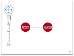
The simple Hello World chart you should see

Earlier this year Stack Exchange updated their API to version 2.2. You can make up to 300 calls a day from your IP without registering, but if you prefer, you can register for an API key here. This will extend your request limit to 10,000.

We recommend taking some time to read through the top-level documentation, to get a feeling for how the API works.

Download KeyLines

Next, take some time to familiarize yourself with the KeyLines SDK documentation (the four pages listed under ‘Fundamentals’ are generally the best place to start) and then head over to the Downloads page.

In the latest version of the SDK, there’s just one zip file to download and install on the server – including the JS, Flash, font and images files. You can run a quick ‘Hello World’ test using the following code snippet. The ‘Getting Started’ page in the SDK has more detail:

<!-- Load the KeyLines file --><script src="keylines.js" type="text/javascript"></script><!-- Other libraries we want to use, e.g. jQuery --><script src="jquery.js" type="text/javascript"></script><!-- This is the HTML element that will be used to render the KeyLines component -->
<!-- This is the actual code to load KeyLines in the page --><script>// <![CDATA[
var myChart;            // This will store a reference to our KeyLines chart object
      var myChartItems = [];  // This array will store our node and link definitions

      // wait until the fonts are loaded to start
      $(window).load(function () {
        
        // Set the path for the assets
        KeyLines.setCanvasPaths(‘assets/’);
         
        //load the component: specify the id and callback
        KeyLines.createChart('chartID', chartReady);
      });
         
      function chartReady (err, chart) {
        // Store a reference to the KeyLines chart object
        myChart = chart;

        // Use our helper functions to add the node and link definitions
        addNode('id1', 'Hello','#B9121B');
        addNode('id2', 'World','#B9121B');
        addLink('id1', 'id2', '', '#4C1B1B', false);

        // Load the chart with the newly defined nodes and links
        myChart.load({
          type: 'LinkChart',
          items: myChartItems
        });
      }  
 
      // Helper function to add a new node definition to our chart items array
      function addNode(nodeId, nodeTitle, colour){
        myChartItems.push({c: colour, id: nodeId, t: nodeTitle, type: 'node',x: 100, y: 100
            });
      }

      // Helper function to add a new link definition to our chart items array
      function addLink(nodeId1, nodeId2, linkTitle, colour, directional){
        myChartItems.push({a2: directional, c: colour, id: nodeId1 + '-' + nodeId2,
              id1: nodeId1, id2: nodeId2, t: linkTitle, type: 'link'
            });
      }
// ]]></script>

Link KeyLines to Stack Overflow

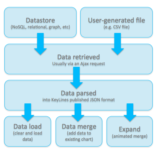
The next step is to get data out of the Stack Exchange API and into the KeyLines chart:

Call the Stack Exchange API

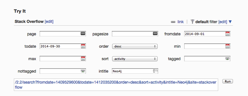
When the user interacts with the data – by expanding a node or dragging the time bar, for example – KeyLines raises an event, triggering a URI request to be sent to the Stack Exchange API. The API contains some handy interfaces to help us understand and construct the URIs we need. For example, to search for questions with ‘Neo4j’ in the title in September 2014: SE interface The following code snippet explains how to send an AJAX request for data to Stack Exchange. We can call the API with difference parameters for ‘query’, for example to send search queries or to make requests for answers to particular questions:

// helper method to send JSONP responses to stackexchange API
var makeReq = function (query, from, to) {
  // http://api.stackexchange.com/docs/throttle
  // stackoverflow takes weird dates (divide normal date by 1000)
  var dates = 'fromdate=' + parseInt(from / 1000, 10) + '&todate=' + parseInt(to / 1000, 10);
  requestsInProgress++;
  setFormEnabled(false);
  // Save a ref for the request, later will use it to fetch and merge the data all together
  var promise = $.getJSON('http://api.stackexchange.com/2.2/' + query + dates + '&site=stackoverflow&callback=?')
  // on Error
  .fail(reportError)                                                                                                                                                                                                                                                            
  // on Success
  .done(updateRequestsRemaining)
  // things to do on every request
  .always(function () {
    requestsInProgress--;
  });
  return promise;
};

Get a response

KeyLines requires the data to be loaded as a JSON object. The Stack Overflow API removes the need for too much data processing by returning responses in JSONP format, like this:

{
      "tags": [
        "neo4j",
        "cypher"
      ],
      "owner": {
        "reputation": 55,
        "user_id": 2796181,
        "user_type": "registered",
        "accept_rate": 10,
        "profile_image": "https://www.gravatar.com/avatar/13838b5fd7185171816d3785d2671478?s=128&d=identicon&r=PG&f=1",
        "display_name": "shree11",
        "link": "http://stackoverflow.com/users/2796181/shree11"
      },
      "is_answered": true,
      "view_count": 30,
      "answer_count": 2,
      "score": 1,
      "last_activity_date": 1412191783,
      "creation_date": 1411973893,
      "question_id": 26094122,
      "link": "http://stackoverflow.com/questions/26094122/tracking-the-history-of-nodes-in-neo4j",
      "title": "Tracking the history of nodes in neo4j"
    },

…but we still need to parse the object into KeyLines’ own JSON format containing nodes and links. This is done by the following code:

// convert the stackoverflow response into data usable by KeyLines
var makeDataFromQuestions = function (questionData) {
  var chartData = [],
    date,
    questionNode;
  _.each(questionData.items, function (item) {
    // convert dates because stack exchange dates are missing digits!                                                                                                                                                                  date = item.creation_date * 1000;
    questionNode = {
      id: item.question_id,
      t: item.title.substring(0, 30),
      c: col.blue,
      type: 'node',
      d: {
        type: 'question',
        fullText: item.title,
        isTruncated: item.title.length >= 30
      },
      g: [
        {c: col.red, t: '' + item.answer_count, p: 'ne'}
      ],
      v: item.answer_count,
      dt: date
    };
    // next we call a function which will make user nodes and link them to the question
        // OR alternatively it will update an existing user's dates (for time bar selection) and add an extra link
    var user = createOrUpdateUser(item, 'owner');
    chartData.push(questionNode);
    chartData = chartData.concat(user);
  });
  // return an object which we can then load or merge into both the time bar and chart
  return {
    type: 'LinkChart',
    items: chartData
  };
};

Every node and link (or, if we were to use them, shape, annotation, glyph and halo) has a unique identity (‘id’ property) and series of attributes.

Display your chart and time bar

All that’s left to do now is display our chart and time bar.

Only one JSON object is required for both the chart and the time bar components. The time bar requires a ‘dt’ attribute to load items by date, and this attribute is safely ignored by the main chart.

Time Bar Merge

The new time bar ‘merge’ function allows developers to add extra data into the time bar while keeping existing data intact.

The Stack Overflow API currently only returns 30 results at a time, so fetching and merging data incrementally like this enables us to build up a complete picture of a topic in a single chart.

To do this, we need to send two requests to the Stack Overflow API – the first to call all the questions on a topic within the given date range, the second to query for the answers to those questions. If the user zooms out using the time bar, KeyLines sends four queries – two for each end of the date range.

In order to nicely handle updating the chart and timebar after an unknown number of requests have been made, we make use of jQuery’s promise feature. When some of the data returned contains users we have already added to the chart and time bar, we simply create new links for this user and update their ‘dt’ field (dates) so that time bar selections can be updated for the new dates:

Style your application

So, there it is. In just a short amount of time, it’s possible to create an interactive graph visualization application using an external API and the KeyLines SDK.

The next step is to play with the design of your application, styling the nodes and exploring layout and analysis options – adding value to the data being explored, depending on the questions you’re trying to answer.

Explore your data

An interesting use for this kind of application is to find active contributors and experts on a given topic. We took a look at some Graph Databases that are active on Stack Overflow. Click any image to expand:

OrientDB: When looking at an overview of all questions with 'OrientDB', we can see that the vast majority of questions (blue nodes) are being answered by one account. OrientDB: Lvca also has the highest number of 'accepted answers' - meaning he is providing information the community deems accurate and valuable. Neo4j: On first glance, the Neo4j community seems larger, with a lot of accounts just answering one or two questions each. On the left hand side we can see some clusters of accounts and questions. Neo4j: Here we can see some dedicated community contribution from Michael Hunger and Peter Neubauer. Titan: The Titan community appears again to be more spread out, with workload shared between the Aurelius team. Titan: Here we can see Stephen Mallette's contributions. The red line shows his answers peak around the end of 2013. Graph Visualization: When visualizing broader topics, for example this chart shows a search for Graph Visualization, answers are less likely to be dominated by individual accounts. Graph Visualization: We can easily find individual questions that have attracted a lot of answers.

Try it yourself

If you’d like to try this for yourself, you can find the demo and source code detailed in this blog post in the KeyLines SDK under Demos > Time Bar > Fetch and Merge.

Get in touch for access to the SDK.

The post Visualizing Stack Overflow appeared first on .

The Future of Graph Visualization

$
0
0

graphconnect logo

There are just a few days to go until GraphConnect SF 2014!

Needless to say, we’re pretty excited about spending some quality time with fellow graphistas, learning more about graph databases and discussing your visualization challenges.

For GraphConnect attendees, there’s going to be plenty of opportunity to see KeyLines in action – not least at 12pm in the main auditorium, where KeyLines creator Joe parry will be giving his talk on the future of graph visualization.

Take your Neo4j visualization to the next level

Joe’s presentation will be filled with live demos, showing how graphs really are everywhere – from Twitter to healthcare fraud. Visualizing these graphs allows us to understand what’s happening inside our data, helping users learn and make the right decisions.

But the reality is that graph data is rarely static. Graphs evolve and reshape constantly. All the time, new connections are made, old relationships dissolve, and new groups form.

Joe’s presentation will show examples of these ‘dynamic’ graphs, explaining how understanding their evolution is the key to gaining real insight and predicting future events.

A picture says a thousand words

Until now, visualization techniques for dynamic graphs have focused on a snapshot approach – taking one cut of the data and comparing it to another. Whilst this is valuable, it’s also hugely time consuming and lacks granular detail.

This problem of dynamic graph visualization has kept many university researchers occupied over the years. Joe will introduce some of past attempts to visualize dynamic graphs, ranging from the quite effective to the baffling…

graphviz

… Before introducing our own solution.

We’ve spent months trying to perfect the art of web-based graph visualization. We’re pretty proud of what we’ve achieved and we know it’s going to inspire you to take your Graph visualization to the next level.

KeyLines Github

If you want to know more, join us: 12pm, October 22.

How to find us at GraphConnect

Joe, Andrew and Corey will be in San Francisco for next week’s Graph Connect. Get in touch to arrange a meeting with any of us, or you can:

  • Hear Joe Parry in the main auditorium
  • Catch Corey Lanum, on the graph visualization panel after lunch
  • Head over to the KeyLines stand during the breaks (remember to leave your details to win a Moto360 smart watch)
  • Stop one of us by the bar at the GraphParty during the evening;

We look forward to meeting you!

The post The Future of Graph Visualization appeared first on .

The Future of Web Applications, Boston

$
0
0

On the 29th October, our data visualization expert Corey Lanum, will be speaking to an audience of JavaScript enthusiasts about browser-based network visualization at the Future of Web Apps conference in Boston. Here’s a sneak peak of what he’ll be covering.

If you want to find out more, you can get a 15% discount off the conference ticket price by quoting ‘KEYLINES’ when booking: https://futureofwebapps.com/boston-2014/register/


The Rise of Web Application

Employees across the world, in all kinds of industries, are demanding more flexibility in how they work. Gone are the days of installing software and tying someone down to a single machine. Modern web technologies are being employed to complete tasks that were previously the reserve of heavy desktop tools, giving users the ability to access their work from any device and (almost) any location.

Network visualization – sometimes called link analysis – is no exception. Software long favored by analysts and data scientists is being pushed aside for a new generation of tools that provide powerful and sophisticated data visualization and analysis

Liberated from the desktop, these lightweight data visualization applications are easy to deploy, maintain and access. But how do you set about building these applications? What user tasks are better performed client-side vs. server-side?

That’s the topic for my presentation at the Future of Web Apps show.

Harness the Canvas

My first piece of advice would be to understand the HTML5 Canvas element – the part of HTML5 that lets you render 2D images and shapes in a web browser. By creating multiple canvases, it’s possible to render and animate entire charts of interactive data visualizations.

The Canvas also provides an easy way to complete a range of different visual effects. Based on our experience of building the KeyLines network visualization web SDK, I’ll show you some of these and how they can enhance your data visualization application.

Build up speed with JavaScript

To ensure a fluid experience for the end user, you need to maintain a frame rate of 60fps – giving you 16ms to render everything. There are some tips to achieve this – from optimizing code to choosing the right JavaScript engine and methods.

I’ll cover some of these tips too, and give some examples of just how powerful, but potentially tricky, JavaScript can be.

Make sure you catch me on day 2 at Future of Web Apps, Boston – I look forward to seeing you there!

The post The Future of Web Applications, Boston appeared first on .


Graphing GitHub

$
0
0

Joe at GCA few weeks ago, we had the opportunity to speak about KeyLines and graph visualization at GraphConnect SF 2014.

The 700+ graphistas in attendance needed no convincing about the power of graphs. The “Graphs are everywhere” maxim has long settled into the collective conscious of the Neo4j community, sparking a whole ecosystem of startups, services and tools as well as a wave of innovation across big business.

But what about data that isn’t inherently graphy? We wanted to show the benefit of visualizing data that we don’t automatically think of as a graph, using KeyLines.

Given an audience of Neo4j enthusiasts, we decided to look at Neo4j itself. This blog post shows how we used the GitHub API to visualize how Neo4j’s is built and maintained.

What is GitHub?

github-octocatFirst, some background:

GitHub is an online service for sharing and publishing code. It allows teams to collaborate on projects and easily manage revisions using three functions:

  • Forking – copying a repository from one user to another.
  • Pushing / pulling – managing revisions back to the project repository.
  • Merging – to merge the changes back to the main repository.

With 17 million repositories and 7.5 million users, great rivers of data are flowing through GitHub every second. The potential for insight into how projects and teams work is huge.

Existing visualization

For some inspiration, we took a look at the data visualization options already available in GitHub. Mostly, they focus on standard quantitative measures:

GitHub data visualization - punch card activity through time

Heat maps and punch cards show detail on what’s happening and when

Github data visualization - repo netowork graph

A network chart attempts to summarize different branch histories

GitHub data visualization - activity by day

Never push on a Friday

GitHub data visualization - repo activity

Contributor charts can show when the highest volumes of contributions were made

But what’s missing here?

Focusing on the contributors and files in isolation means we’re missing an entire dimension of data insight. Including the relationships between different entities enables a richer, deeper analysis of our GitHub data.

Building the graph visualization application

To build our application, we broadly followed five steps: gather, model, design, refine, and interact.

Gather

GitHub has a great API that enables the extraction of data about specific code repositories and users. For easy demonstration purposes we decided to visualize just the last 10 days of commits to the Neo4j repository. (That said, there’s no reason that the whole repository could not be visualized in KeyLines. It would just need a bit more work to prevent excessive visual noise and sensible AJAX calls to allow users to drill down into the large amount of data.)

The information we gathered related to commits within a specific time period and the meta information relating to the commits (represented as links in the chart) as well as the files modified and users responsible for the commit (each of which were represented as nodes in the chart).

Model

Converting flat data to a graph model can be complicated. There are many different combinations in which entities can become nodes, links or properties of nodes and links. The questions you want to ask of your data should define the model used.

More detail on this process is in our blog post Building Great Network Visualizations.

We decided to look at the relationships between individual contributors and files within a single repository, meaning we could sketch this basic model:

GitHub graph data model

GitHub collaboration mapped to a graph structure: contributors and files are nodes, links are commits. Links are colored dynamically from a scale of red to green, where red means the commit has removed more lines than added lines, green means the commit has added more lines than removed lines and yellow has roughly equivalent additions/removals.

Represent

Data slurped and model (loosely) defined, we can get start building the application.

(More detail on this can be found in our SDK documentation Getting Started page. Contact us for an evaluation if you don’t have access to the SDK site.)

We made a few design and functionality decisions early on:

  • All the data was time-stamped, so incorporating the time bar was a no-brainer.
  • To give the application a different ‘look and feel’, we decided on a black background to the chart and time bar.
  • Most commits have a mix of deleted and added lines, so we wanted to color links on a red-green scale programmatically.
  • Contributor and file icons would be extracted from the GitHub API.

1 - GitHub graph visualization

Refine

Basic application running, we set about refining the behavior and tweaking the appearance. We’ve found the best way to do this is through basic UAT. Giving the app to someone who hasn’t used it before and asking them to answer some questions.

From this we learnt we needed to:

  • Add the option of sizing the file nodes by the degree of commits:

file sizing

Glyphs on links

  • Highlighting sub-networks of nodes and links by ghosting everything not selected:

subnetwork-ghosting

  • The ability to double-click nodes to link to GitHub files and profiles.

So, what can we learn from the graph?

Now we have a functioning graph visualization application populated with10 days’ worth of repository data. But what can we actually learn with this tool?

Activity over time

The time bar offers an instant view of commit volume through time. But unlike the charts provided by GitHub, the time bar allows instant filtering of the time range to investigate peaks and troughs in productivity.

On October 13, a maintenance version (1.9.9) was released, and we can see the flurry of commits taking place the Friday before:


Find important files, and see who’s been working on them

This BackupServiceIT.java file was one of the most heavily edited according to our data. Selecting it, we can see who has contributed, how many lines each contributor added or deleted, and also click through to the file to dig deeper.

backup it java

Likewise, ExpandPlanningIntegrationTest.scala had four contributors during this time period. The time bar shows a red selection line indicating commit activity for this particular file versus total commits in the project (grey bars).

From this data we could reasonably surmise that some core and/or refactoring changes were being made by the contributors and they updated this test file accordingly.

testing file sub network

Understand team structures and expertise

Often in open source projects, teams can be formed organically. Viewing collaboration as a graph visualization emphasizes these team structures. In this graph, we can find three distinct teams:

Java

java

Scala

scala

Front-end

front end

We can learn more by watching these relationships over time. For example, here are two devs working together on Scala files over the course of a week:

Githib demo


Watching the second relationship over time, we can see each developer working independently on files before partnering.

Try it yourself

Obviously, we’re only looking at a tiny subset of the data available here, but in about a day we were able to build a functioning visualization application to help us understand how a team and a project is working.

If you would like to try it for yourself, just get in touch – we’d love to hear from you.


The post Graphing GitHub appeared first on .

Detecting loyalty fraud among frequent flyers

$
0
0

When fraud is mentioned, our minds usually jump to a few well-known categories: identity fraud, mail fraud, credit card fraud, etc. But new kinds of fraud are emerging all the time. In this post we take a closer look at loyalty fraud.

What is loyalty fraud?

Loyalty fraud is when programs run by organizations to encourage brand loyalty are abused or manipulated for unfair gain.

It can range from friends sharing supermarket reward cards, to insiders manipulating computer systems to reallocate air miles. Loyalty fraud is a real crime that is costing organizations, but it has been largely ignored by technology vendors.

So, how big is the problem?

Some numbers:

  • $48bn of loyalty credit is sitting unclaimed.
  • Fraudsters have exploited 72% of airline frequent flyer programs.
  • It’s estimated 80% of frequent flyer fraud is discovered by accident.

How does it happen?

Broadly, there are three ways loyalty fraud happens:

  • The insider threat – when a member of staff charges their own account with customer credit or manipulates IT systems to collect credit. One IT analyst at a UK supermarket managed to fraudulently collect millions of points before being detected.
  • Organized crime – criminals use well-known phishing methods, or other forms of social engineering, to collect the information required to empty loyalty accounts. Often these are cashed in for goods or tickets that can be sold on to unsuspecting individuals.
  • Customer fraud – when customers share or pool loyalty credits against the terms of their scheme, or simply break the rules to gain more points than they are entitled to – for example, claiming air miles twice for a shared-revenue ticket.

And here’s the real kicker: the customers most likely to be affected by loyalty fraud – either as victims, or mis-identified as offenders – are those with the most credit and the highest levels of account activity: in other words, your best and most loyal customers.

How can we tackle loyalty fraud?

Fraud detection is a complex problem. Most transactions are genuine, so a process to find the small percentage that is fraudulent requires a robust and large-scale approach to data analysis.

That said, with the right technology and approach to data modeling, it becomes much simpler to recognize signs of loyalty fraud.

Loyalty fraud as a graph visualization problem

Fraud almost always involves the fabrication of a link – between an individual, a transaction, an account, etc., so it makes sense to model data in a way that emphasizes those links.

Using graph visualization, we could find indications of fraud, including:

  • Unrecognized devices
    This is especially telling if changing account details are changed or large transactions performed from a new device.
  • Small transactions followed by larger ones
    This can be a sign of testing the waters before trying to cash in a large number of credits.
  • Account access from multiple locations
    A tough criterion to check for a frequent flyer program (you expect customers to move around!) but if a customer is accessing their account from Mumbai and London within an hour of each other, it should raise a flag.
  • Buying tickets with multiple names
    Or changing the name on a ticket purchased with points. Often fraudsters will sell ill-gotten airline tickets using online message boards or auction sites, changing the name afterwards.
  • Unusual access patterns to the customer loyalty database
    If a staff member is manipulating the system, you should be able to find evidence in server logs.
  • Repeated unsuccessful login attempts to the rewards website
    This could be individuals or phishers trying to crack an account.

See the big picture

Using some mock data for a Frequent Flyer program, we built an application for visualizing and detecting cases of loyalty fraud.

There are three entities we’re interested in:

  • Accounts
    • Account ID
  • Transactions
    • Transaction time
    • Transaction value
    • Transaction IP
  • Tickets
    • Ticket ID
    • Ticket departure airport
    • Ticket arrival airport

Which we can map to the following data model:

loyalty fraud - frequent flyer - data model


When we take data from a ‘clean’ account and apply this model, this is the sort of structure we see:

Non-fraud overview


What does this show?

The time bar here is showing two metrics: the grey histogram is the volume of transactions (both credits and debits), the red series link is the value of debits from the account.

The flow of transactions is steady, the value of debits is unsuspicious: two small debits in February and June, a larger one in December.

In the chart, we can see this account always travels from London Heathrow to busy business hub airports – Paris, New York, Frankfurt.

So far, so uneventful.

Frequent Flyer Fraud

Fraud - overview

Just a quick glance shows that this account doesn’t match the norm.

Firstly, take a look at the spike of transactions in October. If we zoom in, the majority of them took place on one day in under 20 minutes, including two small transactions in quick succession followed by 6 much larger ones:

Fraud 4-15 to 4-35


We can also see two IP addresses at play here. The first one associated with four tickets between LAX and PDX, as well as a steady stream of credits:

Fraud - a normal trip

The second IP was used to purchase 8 tickets, mostly for journeys outside of the US:

Fraud overview - foreign IP


Clearly this is just a simple example using a small amount of synthesized data, but it shows the potential.

When looking at large volumes of fraud data, and it’s often the connections that tell the story. Using graph analysis and visualization techniques, hidden details and insight can be uncovered, allowing for security and process loopholes to be detected and individuals to be prosecuted.

Despite the significant potential for financial loss and reputation damage, loyalty fraud remains an area of low priority for fraud technology vendors.

To find out more about how KeyLines can be used to help companies detect fraud and reduce financial losses, get in touch or download our Fraud White Paper:

The post Detecting loyalty fraud among frequent flyers appeared first on .

Building a data visualization app in Java

$
0
0

spring1Earlier in this blog, we went into some detail on how to integrate KeyLines’ network visualization capability into a Java application using Google Web Tools (GWT).

As part 2 in the series, we explain how to get KeyLines data visualization capability running in your Spring project.

Step 1: Understand Spring

There’s no shortage of Java frameworks out there, trying to tempt overstretched enterprise developers, crying for help from beneath their mountains of code. Top of the pile, in terms of market share at least, is the Spring framework.

Spring is a simple, stable and elegant platform for Java applications. In its own words, Spring ‘handles the infrastructure so you can focus on your application.’ It makes the process of building an enterprise web application with rich front-end simpler, faster and much less code-heavy.

With Spring you can either use regular POJOs or Spring Beans to model the logic, making integration with other frameworks as simple as possible – including the Spring Data Neo4j, a delightful project that makes building Java graph applications on top of your Neo4j graph database simpler.

Step 2: Start the Spring tutorial

One of the best things about Spring is how simple it is to start a project:

  1. Choose Spring Starter Project
    Spring starter project
  2. Choose a name for the project
    Spring project name
  3. Tick the ‘web’ checkbox in the panel at the bottom.

You should end up with most of your application code and the following file structure (shown in an Eclipse environment):

Spring file structure

Once you’ve created the project, add the WebController file (see step 3) and the index.html in the resources folder (see step 4).

Step 3: Create the controller class

Next up, you need to create a simple controller class to serve the HTML page:

package your.application.controller.package;
import org.springframework.stereotype.Controller;
import org.springframework.web.bind.annotation.RequestMapping;
import org.springframework.web.bind.annotation.RequestMethod;
import org.springframework.web.servlet.config.annotation.WebMvcConfigurerAdapter;
@Controller
public class WebController extends WebMvcConfigurerAdapter {
    @RequestMapping(value="/", method=RequestMethod.GET)
    public String showPage() {
        return "index";
    }
}

Step 4: Serve your web page

The Controller will serve the following index.html file containing the KeyLines component, which is insides rc/main/resource/template

<!DOCTYPE HTML>
<html>
  <head>
     
    <meta http-equiv="Content-Type" content="text/html; charset=UTF-8" />
    <link rel="stylesheet" type="text/css" media="all" href="css/fonts.css" />
    <script type="text/javascript" src="js/keylines.js"></script>
    <script type="text/javascript" src="js/jquery.js"></script>
    <script type="text/javascript" src="js/data.js"></script>
  </head>
  <body>
    <h1> Spring and KeyLines together!</h1>
    <div id="kl" style="width: 650px; height: 400px;" ></div>
    <script type="text/javascript">
    var chart;
    
    $(window).load(function(){
      // let KeyLines decide which renderer fits better
      KeyLines.mode(‘auto’);

      KeyLines.paths({ assets: ‘/assets/’});

      // pass the callback to be called when the creation will be completed
      KeyLines.create(‘kl’, chartLoaded);
    });

    function chartLoaded(err, newChart){
      chart = newChart;

      // from here on you can use the KeyLines chart component. getData is a function in js/data.js file, but could also be e.g. a call to web server.
      chart.load(getData());
    }

    </script>
  </body>
</html>

Step 5: Run your application

Run the application from the IDE – we use Eclipse here – and point your browser to http://localhost:8080/:

final-step

And that’s it!

screenshot data visualization in spring

In five simple steps we’ve got KeyLines running in a Java environment.

If you would like an evaluation of KeyLines to give it a go for yourself, just get in touch with some information about your project. We’d love to hear from you!

The post Building a data visualization app in Java appeared first on .

KeyLines News – November 2014

$
0
0

Just over a month ago, the KeyLines team took a trip to San Francisco to join GraphConnect SF 2014. The good news for those who weren’t able to make it is that the entire conference can now be re-lived online!

Don’t forget to catch the following highlights:

pre-release-large

The unchecked world of frequent flyer fraud

This month our blog introduced a kind of fraud that’s rarely discussed but that could be costing millions of dollars each year: loyalty fraud.

Tracking Down the Lost Millions shows how graph visualization technology can be used to uncover theft from frequent flyer programs. It’s worth reading alongside our white paper, Catching Fraudsters with Network Visualization.

KeyLines for Java Developers

Are you building a web app in Java? Our latest blog post is perfect for you!

The snappily-titled Building a network visualization application in Java, Part 2: The Spring Framework will help you on your way. Part 1 in the series, covering KeyLines and GWT, can be found here.
SVC2uk-lse

Joining the Scale Up Club

Last week we learned that Cambridge Intelligence is officially one of the fastest-growing startups in the UK. More news coming soon!

Also, we wanted to thank you for voting for use for the Start Ups awards. Voting is now closed and we find out later this week if we’ve been successful. Follow us on Twitter to hear the news first!

Join our team

Cambridge Intelligence is growing! We offer great benefits, an awesome place to work,lovely colleagues and the chance to try new things in a fast-growing company. Find out more.

Best wishes

The Cambridge Intelligence team

The post KeyLines News – November 2014 appeared first on .

KeyLines FAQs: Social Network Analysis

$
0
0

Essential to good network visualization is a set of tools to cut through noise and hone in on the important parts of a network.

One way to do this is using social network analysis – a way of understanding social dynamics in a network. Specifically, centrality measures can help find the important people in a network.

This FAQ explains, as concisely as possible, the three most important centrality measures and when they should be used.

Degree Centrality

degree-centrality

A network of terrorists, repeatedly filtered by degree (also known as a k-degenerate graph) revealing clusters of tightly-connected nodes

Definition: Degree centrality counts the number of links held by each node.

What it tells us: How many direct, ‘one hop’ connections each node has to other nodes within the network.

When to use it: For finding very connected individuals, popular individuals, individuals who are likely to hold most information or individuals who can quickly connect with the wider network.

A bit more detail: Degree centrality is the simplest measure of node connectivity. Sometimes it’s useful to look at indegree (number of inbound links) and outdegree (number of outbound links) as distinct measures, for example when looking at transactional data or account activity.

Betweenness centrality

betweenness-centrality

A Twitter network, with nodes sized by betweenness

Definition: Betweenness centrality measures the number of times a node lies on the shortest path between other nodes.

What it tells us: This measure shows which nodes act as ‘bridges’ between nodes in a network. It does this by identifying all the shortest paths and then counting how many times each node falls on one.

When to use it: For finding the individuals who influence the flow around a system.

A bit more detail: Betweenness is useful for analyzing communication dynamics, but should be used with care. A high betweenness count could indicate someone holds authority over, or controls collaboration between, disparate clusters in a network; or indicate they are on the periphery of both clusters.

Closeness centrality

closeness-centrality

A corporate email network; nodes with a high closeness degree are enlarged

Definition: This measure scores each node based on their ‘closeness’ to all other nodes within the network.

What it tells us: This measure calculates the shortest paths between all nodes, then assigns each node a score based on its sum of shortest paths.

When to use it: For finding the individuals who are best placed to influence the entire network most quickly.

A bit more detail: Closeness centrality can help find good ‘broadcasters’, but in a highly connected network you will often find all nodes have a similar score. What may be more useful is using Closeness to find influencers within a single cluster.

Read more about visualizing social networks

We’ve produced a white paper explaining how to visualize social networks with KeyLines. Download a copy here »

The post KeyLines FAQs: Social Network Analysis appeared first on .

Viewing all 507 articles
Browse latest View live


Latest Images